Adaptive Optics Using SWIR Cameras
In order to image long distances through the atmosphere, a method is required to compensate for the turbulence in the air that is caused by variations in the temperature of the air along that path. Adaptive optics have been developed to compensate for this problem using specialized hardware, such as a Shack-Hartmann Wavefront Sensor. The sensor measures the differences in optical intensity of a reference laser beam and uses the information to provide feedback to a deformable mirror type system.
This kind of system is important for high quality astronomical imaging from earth based telescopes. It is also important for guided laser beam applications such as Free Space Optical Communications where a modulated laser bean is used to send high frequency information over gaps of several miles or in the field of defense for High Energy Laser weapons that are now be fielded by the military to counter threats from drones and high speed missiles.
The key for this application is to use a reference laser beam that can propagate long distances through the atmosphere and that is also eye-safe. It is also useful to have a beam that can travel through some amount of water vapor or haze without being scattered and lost. For these reasons, a SWIR wavelength is very useful for this application.
The other key requirement for this application is very high speed – 6kHz or more – in order to provide feedback to drive the deformable mirrors at high speed and maintain a good stable signal. Ideally, this speed should be achievable with at least 128×128 pixels so there are enough data points to provide accurate corrections.
The final element that is necessary is sufficient sensitivity combined with enough maximum signal to allow a high “Figure of Merit” which is defined as the ratio of the maximum signal size (in electrons) to the readout noise squared (measured in electrons). The readout noise is typically a function of the gain state (the electrons per count), with lower noise at high gain states (fewer electrons per count). The maximum signal size is typically defined by the bit depth and the gain state (# bits * electrons/adu), so as the gain is increased, the total maximum signal size in electrons is reduced proportionately. Once you have data on the cameras noise and gain value, you can determine the maximum value for a particular bit depth and therefore the Figure of Merit which should be at least 2 but ideally would be 5-10.
Xenics Cheetah 640 Series
The Cheetah 640 1700Hz camera is well suited for this particular application. It has the following key features that make this application possible.
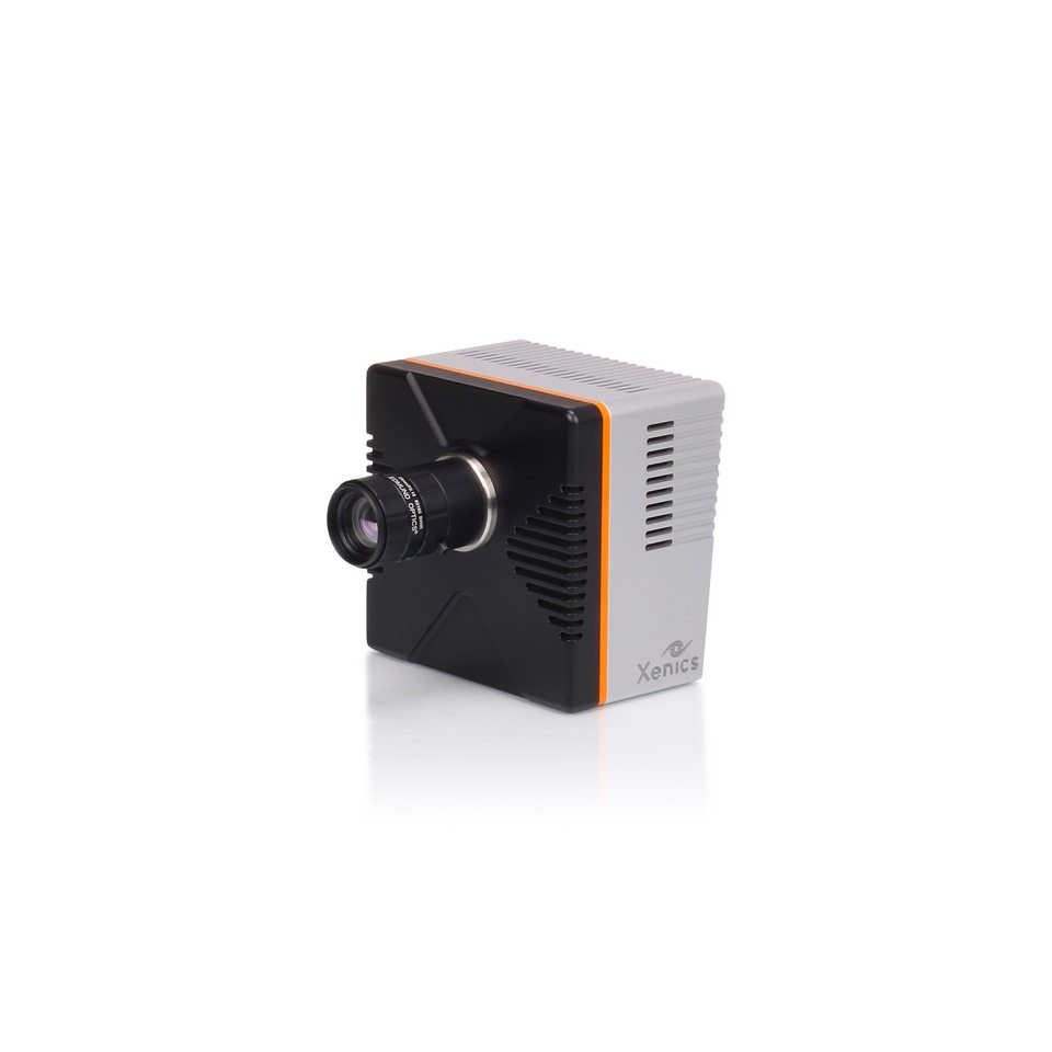
- Highest frame rate SWIR Camera on the market
- Selectable Gain States for optimal operation mode
- Short exposure times
- Can be operated in Triggered Mode to synchronize with the laser pulse
- Cheetah 640 Series Datasheet
- Product information/quote